The PICADC device was presented by "Wojciech Zabolotny" some years ago on his web site: http://www.ise.pw.edu.pl/~wzab/picadc/picadc.html
The data converter is vey low noise, also the needed components are few and it is very easy to build. But the software is only a recorder and run only under LINUX Systems...
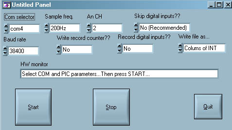
For this reason I have decided to convert the software to run under Windows systems. The win software is linux software like, you can decide the channels number, the sample frequency etc... but you can't decide the channels sample order. The Software include some special features e.g. you can chose the format fo data that will e write on the output data file "DATA.TXT", among "char" (without any interpretation) or colums of integer (remember the data are sapled in reverse order!!!!).
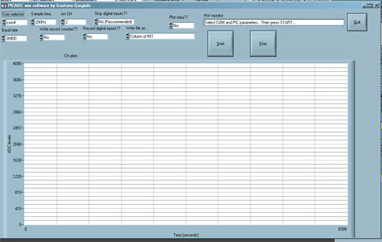
Also I have released a software able to plot the data in real time. There is a delay betwen the file output (highest priority) and the plot. Also the association between colors and channels change with number of sampled channels. The color sequence is: black, yellow, blue, pink, grey, green, red, purple. If you are sampling two channels the asociation is ch1: yellow ch2:
When you press the stop button the program will write a second .txt file with a summary of the configuration used and record the time thet the PICADC has received the start command.
NB: All programs are written in C.V.I. Lab Windows language and are available like source and precompiled. Somentimes if the stop button doesn't work yuo need to turn off the PICADC kill the process with CTRL+ALT+CANC. In this case the last data record is not good and the second file will not generated... Sorry I am workin on...
Coming soon a free RS232 opto-coupler tested with USB adapter and with baud rate of 1115200...
Here there's some screenshot and the links to download the softwares!!!!.
26/03/2007:
I have fixed the STOP problem for all systems, also now the colour table is fixrd and spcified in the user interface!!!
10/04/07:
Clik Here to downoload the opto-insulator schematic in Express PCB format. The circuit works with any kind of RS232, USB adapter included, in this case you need to use the battery (B1).
Disclamer: All the material (excepted the photo) are "AS IS" you fell free to modify and distribuite. I can't be responsable about the use of the material!!!